Week of February 4th
-Complete Calender of Events Due 2/05
-Order Construction Materials
-Begin Layout for for Weblog Portfolio
-Add existing images to weblog portfolio
-Update Log
Week of February 11th
-Begin Construction (if materials are recieved)
-Construction: Cut Material to size
-Visit & Update Mentor
-Update Log
Week of February 18th
-Construction: Cut holes in steel flats
-Update Log
Week of February 25th
-Construction: Begin Welding Process
-Update Log
-Visit & Update Mentor
Week of March 3rd
-Construction: Continue Welding Process
-Begin Work on Press Release
-Update Log
Week of March 10th
-Construction: Finish Welding Process
-Press Release: Write Introduction, Body, Conclusion
-Press Release: Add Applicable Images/Illustrations
-Update Log
-Visit & Update Mentor
Week of March 17th
-Press Release Due 3/19
-Bring Test Vessel to Tech Lab
-Construction: Fitting Product to Vessel
-Update Log
Week of March 24th
-Spring Break
Week of March 31st
-Presentations Begin 4/02
-Prepare for Presentations
-Update Log
-Visit & Update Mentor
-Complete Mentor Contacts
Monday, February 4, 2008

Friday, January 18, 2008
Plan of Procedures
Adjustable Oarlock Design Process
Mounting oarlocks in different spots on a vessel requires a sturdy mounting block, capable of working with the stresses that occur from normal operation. Steel pieces offer the greatest strength for the lowest cost, making it the ideal choice for use in this project. Steel construction will be used throughout, from the mounting block, to the bolts and washers used to secure the assembly to the vessel hull. Knowledge of metalworking, specifically, welding, is required for the project’s success. Several holes must be tapped through solid steel, requiring careful attention to detail by the builder. There are two oarlock blocks required for the project, with both sides undergoing construction simultaneously. If both sides are built at the same time, it will be easier to apply similar techniques to both units instead of finishing one before beginning another.

Plan of Procedures:
A. Material Processing Steps:
1. Receive uncut steel flats in 40” size
2. Measure & cut 40”x 3” x ¼” steel flat into two 20” sections
3. Measure & cut 40” x 1.5” x ¼” steel flats into four 20” sections
4. Measure & cut 1” diameter hole into 3” steel flat
i. Measure 2” from end of flat to center of hole
ii. Measure 2” from center of hole, cut second hole
iii. Repeat cuts: four holes from side
5. Measure and cut access hole for stainless steel bolt
i. Measure 10 inches from center
ii. Cut hole wide enough for SS Bolt
6. Measure and cut 1” diameter hole for remainder of flat
i. Measure 2” from center of SS Bolt hole
ii. Cut 1” diameter hole in flat
iii. Repeat cuts: four holes from center
7. Repeat steps 4-6 for second 3” steel flat
B. Assembly Procedures
1. Clamp 1.5” steel flat at 0.5” from outside of 3” steel flat
2. Weld 1.5” steel flat into place onto 3” steel flat
3. Clamp 1.5” steel flat at 1.5” from outside of 3” steel flat, opposite of first 1.5” flat
4. Weld second 1.5” steel flat into place onto 3” steel flat
5. Repeat steps 1-4 for second steel flat
6. Mount washer and bolt assembly through bolt hole on steel flat
7. Mount completed oarlock assembly to vessel through existing oarlock hole
8. Secure device to boat with attachment of steel nut to stainless steel bolt
C. Finishing Steps
1. Mount desired oarlocks through holes in steel flat
2. Secure oarlocks to steel flat using existing cotter pin system
3. (if present on chosen oarlock)
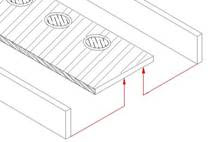


Mounting oarlocks in different spots on a vessel requires a sturdy mounting block, capable of working with the stresses that occur from normal operation. Steel pieces offer the greatest strength for the lowest cost, making it the ideal choice for use in this project. Steel construction will be used throughout, from the mounting block, to the bolts and washers used to secure the assembly to the vessel hull. Knowledge of metalworking, specifically, welding, is required for the project’s success. Several holes must be tapped through solid steel, requiring careful attention to detail by the builder. There are two oarlock blocks required for the project, with both sides undergoing construction simultaneously. If both sides are built at the same time, it will be easier to apply similar techniques to both units instead of finishing one before beginning another.

Plan of Procedures:
A. Material Processing Steps:
1. Receive uncut steel flats in 40” size
2. Measure & cut 40”x 3” x ¼” steel flat into two 20” sections
3. Measure & cut 40” x 1.5” x ¼” steel flats into four 20” sections
4. Measure & cut 1” diameter hole into 3” steel flat
i. Measure 2” from end of flat to center of hole
ii. Measure 2” from center of hole, cut second hole
iii. Repeat cuts: four holes from side
5. Measure and cut access hole for stainless steel bolt
i. Measure 10 inches from center
ii. Cut hole wide enough for SS Bolt
6. Measure and cut 1” diameter hole for remainder of flat
i. Measure 2” from center of SS Bolt hole
ii. Cut 1” diameter hole in flat
iii. Repeat cuts: four holes from center
7. Repeat steps 4-6 for second 3” steel flat
B. Assembly Procedures
1. Clamp 1.5” steel flat at 0.5” from outside of 3” steel flat
2. Weld 1.5” steel flat into place onto 3” steel flat
3. Clamp 1.5” steel flat at 1.5” from outside of 3” steel flat, opposite of first 1.5” flat
4. Weld second 1.5” steel flat into place onto 3” steel flat
5. Repeat steps 1-4 for second steel flat
6. Mount washer and bolt assembly through bolt hole on steel flat
7. Mount completed oarlock assembly to vessel through existing oarlock hole
8. Secure device to boat with attachment of steel nut to stainless steel bolt
C. Finishing Steps
1. Mount desired oarlocks through holes in steel flat
2. Secure oarlocks to steel flat using existing cotter pin system
3. (if present on chosen oarlock)


Thursday, January 10, 2008
MST Report
Math, Science & Technology:
Adjustable Oarlock
Upon completing the design of the final solution, there is often abundance in the amount of science and mathematics used to develop the project. In solving the question of an adjustable oarlock, a variety of applied sciences were used to better judge the value of the presented solutions. The very design of the final solution comes from simple mathematic equations, combined with use of technology to solve a problem which has no existing remedy. The careful use of science in conjunction with the technology requires a great deal of development, and these developments have been carefully documented in this paper. From the basic equations used to form the outline of the chosen solution, to the careful study of ergonomic and biometrics, which lead to the small details present in the final model, and includes the technology which has been designed as a result of the application of science.
The leading scientific cause that concerns the use of an adjustable oarlock is that of ergonomics. Comfort, or lack thereof, is of primary concern for the user of this product. If the adjustable oarlock is awkward to use or otherwise ungainly, there is no reason to continue using it. Human beings come in a variety of sizes, and products which cannot cater to this broad spectrum will fail in an open market. The adjustable oarlock has been designed from the outset to be a product which can be easily used by many types of rowers, and its very purpose is to improve upon the rigid and anti-ergonomic design of the original, basic oarlock. The final design is anthropometrically sound, and includes features which are not limited by user size and body type. The final model presents a product that can be easily adapted to any user requirement, with quick and easy adjustment. Ergonomically, the mechanism must conform to the hull patterns of a wide range of vessels, and must also project no dangerous points or contain any sharp protrusions that may inadvertently injure the operator during normal operating procedures. Since the oarlock is attached to the boat using a nearly universal socket/bolt system, there is little doubt as to the products ability to be used in a wide range of vessels, expanding the suitable application of the adjustable oarlock.
It was equally important to consider the biometric factors of design, as the adjustable oarlock is simply an improvement over an existing technology. If a customer spends the money to purchase an adjustable oarlock, it is assumed that they already have a vessel which uses standard oarlocks, so the adjustable product must justify the expenditure of additional capital, as typical oarlocks are an available, cheaper alternative. The improved product must represent a marked improvement over the original design, or the expense cannot be warranted. Building the product out of superior materials and taking careful care to construct using professional methods will only increase the appeal of the product. The adjustable oarlock can be seen as an add-on, but one that is required in order to obtain maximum performance in any vessel designed to be rowed.
The mathematical portion of this project consists of simple arithmetic equations, each one determining how the end product will function. Measurements were taken of each critical aspect of the vessel relating to oarlock function, and these dimensions were used to create the original drawings of the adjustable oarlock. Working with an overall length of 20 inches (shown in Fig 1), determined to be the ideal length when concerned with adaptability among different vessel types. A shorter length may prove unstable, and a longer length may cause compatibility issues. Inside these 20 inches, multiple holes are to be drilled, with equal spacing between each hole. The final design offers a one inch diameter hole, with two inches from each center of the hole to the next. This configuration was utilized due to the limited space and a desire for symmetry. With four holes on either side of a central bolt, the final design presents a clean, streamlined design. Mathematics played another role in the design of the final product, when concerning the mounting of the adjustable block to the original vessel. The length of the stainless steel bolt can be changed depending upon the situation (Fig 2), with overall emphasis on a modular design. Everything, from the size of the oarlock mounting holes to the major dimensions of the device, is designed for use among many types of vessels and oar types.
The technology aspect of the adjustable oarlock design relies heavily upon the choice of material. The design can be completed with some degree of success across a large number of material choices, but using an affordable, available material such as steel has many benefits. Using rudimentary welding techniques (Fig 3) in conjunction with various other metalworking tools, the product can be completed quickly, with minimum effort. Other materials, such as aluminum, may be cheaper and easier to work with, but lack the durability required to withstand the pressures of a working within a marine environment. Using quality materials will extend the life of such a product, and ensure that the product will remain in a functional state for years to come.
With the application of science expressed in technology, and a grounding of mathematics to form the standard design of the product, the adjustable oarlock has a great deal of support. The final design is a result of many alternative designs and has been selected from a series of different solutions. The end result is a product which has been refined to best provide for needs of the potential customer, and represents the evolution of ideas from brainstorming to the future creation of a prototypical example.
Adjustable Oarlock
Upon completing the design of the final solution, there is often abundance in the amount of science and mathematics used to develop the project. In solving the question of an adjustable oarlock, a variety of applied sciences were used to better judge the value of the presented solutions. The very design of the final solution comes from simple mathematic equations, combined with use of technology to solve a problem which has no existing remedy. The careful use of science in conjunction with the technology requires a great deal of development, and these developments have been carefully documented in this paper. From the basic equations used to form the outline of the chosen solution, to the careful study of ergonomic and biometrics, which lead to the small details present in the final model, and includes the technology which has been designed as a result of the application of science.
The leading scientific cause that concerns the use of an adjustable oarlock is that of ergonomics. Comfort, or lack thereof, is of primary concern for the user of this product. If the adjustable oarlock is awkward to use or otherwise ungainly, there is no reason to continue using it. Human beings come in a variety of sizes, and products which cannot cater to this broad spectrum will fail in an open market. The adjustable oarlock has been designed from the outset to be a product which can be easily used by many types of rowers, and its very purpose is to improve upon the rigid and anti-ergonomic design of the original, basic oarlock. The final design is anthropometrically sound, and includes features which are not limited by user size and body type. The final model presents a product that can be easily adapted to any user requirement, with quick and easy adjustment. Ergonomically, the mechanism must conform to the hull patterns of a wide range of vessels, and must also project no dangerous points or contain any sharp protrusions that may inadvertently injure the operator during normal operating procedures. Since the oarlock is attached to the boat using a nearly universal socket/bolt system, there is little doubt as to the products ability to be used in a wide range of vessels, expanding the suitable application of the adjustable oarlock.
It was equally important to consider the biometric factors of design, as the adjustable oarlock is simply an improvement over an existing technology. If a customer spends the money to purchase an adjustable oarlock, it is assumed that they already have a vessel which uses standard oarlocks, so the adjustable product must justify the expenditure of additional capital, as typical oarlocks are an available, cheaper alternative. The improved product must represent a marked improvement over the original design, or the expense cannot be warranted. Building the product out of superior materials and taking careful care to construct using professional methods will only increase the appeal of the product. The adjustable oarlock can be seen as an add-on, but one that is required in order to obtain maximum performance in any vessel designed to be rowed.
The mathematical portion of this project consists of simple arithmetic equations, each one determining how the end product will function. Measurements were taken of each critical aspect of the vessel relating to oarlock function, and these dimensions were used to create the original drawings of the adjustable oarlock. Working with an overall length of 20 inches (shown in Fig 1), determined to be the ideal length when concerned with adaptability among different vessel types. A shorter length may prove unstable, and a longer length may cause compatibility issues. Inside these 20 inches, multiple holes are to be drilled, with equal spacing between each hole. The final design offers a one inch diameter hole, with two inches from each center of the hole to the next. This configuration was utilized due to the limited space and a desire for symmetry. With four holes on either side of a central bolt, the final design presents a clean, streamlined design. Mathematics played another role in the design of the final product, when concerning the mounting of the adjustable block to the original vessel. The length of the stainless steel bolt can be changed depending upon the situation (Fig 2), with overall emphasis on a modular design. Everything, from the size of the oarlock mounting holes to the major dimensions of the device, is designed for use among many types of vessels and oar types.
The technology aspect of the adjustable oarlock design relies heavily upon the choice of material. The design can be completed with some degree of success across a large number of material choices, but using an affordable, available material such as steel has many benefits. Using rudimentary welding techniques (Fig 3) in conjunction with various other metalworking tools, the product can be completed quickly, with minimum effort. Other materials, such as aluminum, may be cheaper and easier to work with, but lack the durability required to withstand the pressures of a working within a marine environment. Using quality materials will extend the life of such a product, and ensure that the product will remain in a functional state for years to come.
With the application of science expressed in technology, and a grounding of mathematics to form the standard design of the product, the adjustable oarlock has a great deal of support. The final design is a result of many alternative designs and has been selected from a series of different solutions. The end result is a product which has been refined to best provide for needs of the potential customer, and represents the evolution of ideas from brainstorming to the future creation of a prototypical example.
Friday, December 14, 2007

Friday, December 7, 2007


Wednesday, November 14, 2007
Calender: Marking Period 2
-Transfer AutoCAD Drawings to class
-Edit Orthographic AutoCAD drawings to final solution
-Label Materials in AutoCAD
-Begin work on Isometric View
-Add texture & color to isometric view
-Complete Colored Isometric View
-Begin work on Exploded View in AutoCAD
-Label parts of Exploded View
-Finalize Exploded View in AutoCAD
-Convert drawings to images (.bmp, .jpg)
-Begin Materials Bidding Process
-Visit & Update Mentor
-Fill out Inquiry Form (Bidding Process)
-Fill out Requisition Form (Bidding Process)
-Fill out Purchase Order Forms (Bidding Process)
-Finalize Bidding Process
-Begin work on Plan of Procedures
-Add Materials Processing Procedures
-Add Assembly Procedures
-Add Images, Graphics to Procedure
-Complete Plan of Procedures
-Visit & Update Mentor
Week of December 17th
-Begin work on Materials List, Supply List, Part List
-Add graphics to Materials List et al.
-Add 3D Image to Materials List
-Complete work on Materials List, Supply List, Part List
-Development Work Due 12/19
-Bid Process Due 12/19
Week of December 24th
-Winter Holiday-Type Siesta Break
Week of January 2nd
-Begin Math & Science Report
--Write Introduction
--Describe Science Concepts that apply
--Describe all mathematical computations that apply
--Describe all of the technology involved in solution
--Write Conclusion
-Visit & Update Mentor
Week of January 7th
-Prepare Project for Formal Presentation
-Mathematics/Science Report Due 1/10
-Visit and Update Mentor
Week of January 14th
-Practice 5 Minute Formal Update
-Presentations Begin: 1/17-1/21
-Mentor Contacts due 1/23
Tuesday, October 30, 2007
Model Pictures
Model
The model of the final solution was constructed in the course of a week, with perhaps one hour of total build time. The model was constructed using simple and cheap materials, utilizing balsa wood and hot glue avalibile to all students in Systems class. After the frame was constructed, I cut up a length of PVC into small sections, which were added to the model with more hot glue. I completed the model by adding a metal bolt and spray painting the entire assembly a metallic, chrome style spray paint. The results of the construction are as follows:

Front View of Completed Model

Bottom View of Model

Closeup View of Bolt Assembly

Closeup View of Bolt Top

Side View of Completed Model
The model of the final solution was constructed in the course of a week, with perhaps one hour of total build time. The model was constructed using simple and cheap materials, utilizing balsa wood and hot glue avalibile to all students in Systems class. After the frame was constructed, I cut up a length of PVC into small sections, which were added to the model with more hot glue. I completed the model by adding a metal bolt and spray painting the entire assembly a metallic, chrome style spray paint. The results of the construction are as follows:

Front View of Completed Model

Bottom View of Model

Closeup View of Bolt Assembly

Closeup View of Bolt Top

Side View of Completed Model
Subscribe to:
Posts (Atom)